fastrobots
This is my repository for ECE 4160: Fast Robots at Cornell University during the Spring 2025 semester.
This project is maintained by vs356
Lab 3: Time of Flight Sensors (Due 2/25/2025)
Prelab
- The default sensor address of both Time of Flight (ToF) sensors is 0x52, but the address is also programmable.
- Since the two sensors cannot be addressed individually, we can change the address programmatically (while powered) or continuously enable/disable the two sensors separately through their shutdown pins. While continuously enabling/disabling the sensors can be timed well to ensure that all obstacles around the robot are detected using the programmable field of view of the sensors, I believe that this approach would be too error-prone to begin with, so I will elect to change the address of one ToF sensor by shutting down one sensor, changing the address of the other sensor, and continuing the program with independent I2C addresses.
- I plan to place the sensors on the front and back of the car, and detect obstacles on the sides by turning the car. I selected a symmetric orientation because I found that the car can flip over and turn in place very quickly and easily: I wanted to select an orientation that would allow the car to continue to obtain reliable readings regardless of the current orientation of the car.
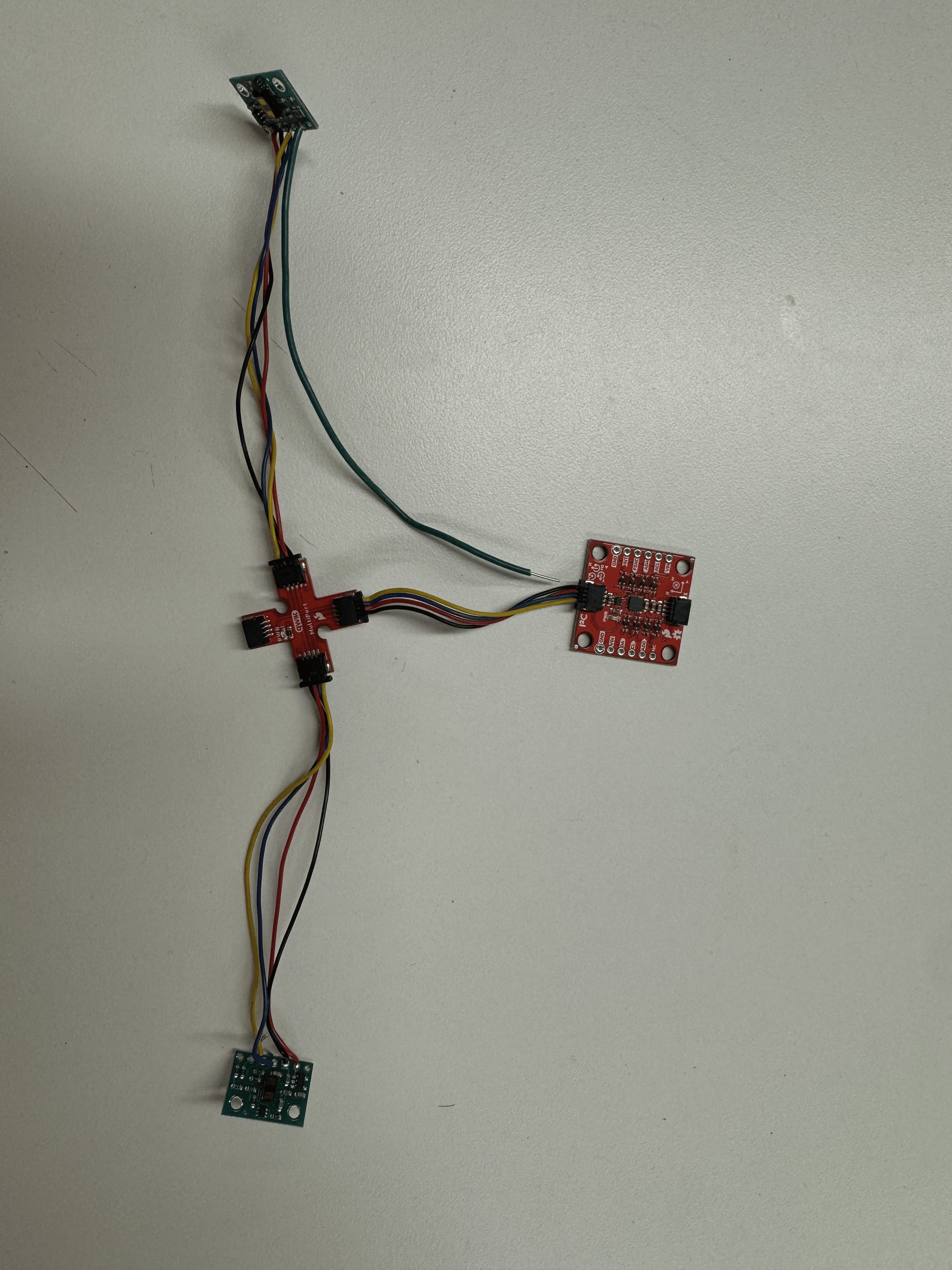
- The two shortest QWIIC cables connect the RedBoard Artemis Nano to the QWIIC breakout and the QWIIC Breakout to the IMU. The two longest QWIIC cables have been separated and soldered onto the ToF sensors (red to VIN, black to GND, blue to SDA, yellow to SCL), and they connect to the two remaining ports on the QWIIC breakout. The ToF sensor that will be placed on the front of the robot has an extra wire soldered to the XSHUT pin and Pin #9 on the RedBoard Artemis Nano. Wiring Diagram (Image)
Lab Tasks
- Image of the ToF sensors and IMU connected to QWIIC breakout board. The RedBoard Artemis Nano connects to the empty port labeled PWR.
- Screenshot of Artemis scanning for I2C device (and discussion on I2C address): The address is shifted from the given address in the datasheet because the final bit of the I2C address is used to indicate whether data is being written (0) or read (1).
- From the chart of distance modes in the ToF sensor datasheet, I elected to use the short-range distance mode. This mode has the least variation due to lighting and the maximum range of 136 cm (~53.5 in, 4.5 ft) seems far enough for the purposes of detecting obstacles, and close enough that the findings are relevant to a very quickly moving vehicle, so the added distance (up to 4m, also according to the datasheet) does not seem to add enough utility in exchange for the added sensitivity to lighting and volume of data stored.
-
2 ToF sensors and the IMU: Discussion and screenshot/video of sensors working in parallel
- Tof sensor speed: Discussion on speed and limiting factor, include code snippet of how you do this: While it is important that data from the ToF sensors are sent and recorded as quickly as possible, the fastest the serial bus on the sensors can transmit data is 400 kHz.
-
Time v Distance: Include graph of data sent over bluetooth (2 sensors)
- Time v Angle: Include graph of data sent over bluetooth